
STUDIO / FEATURES

A design system built around fabrication.

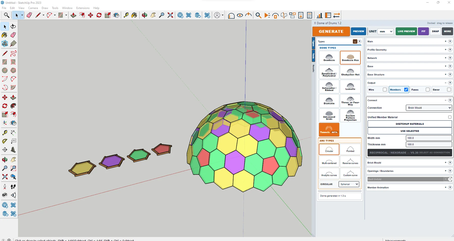
Geometry, physical members, connections, openings, coverings, molds and workshop output are treated as one connected workflow.

CREATE

Dome families & derived structures

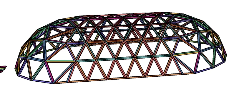
Geometry families are grouped by function.

SUPPORTED GEOMETRY FAMILIES
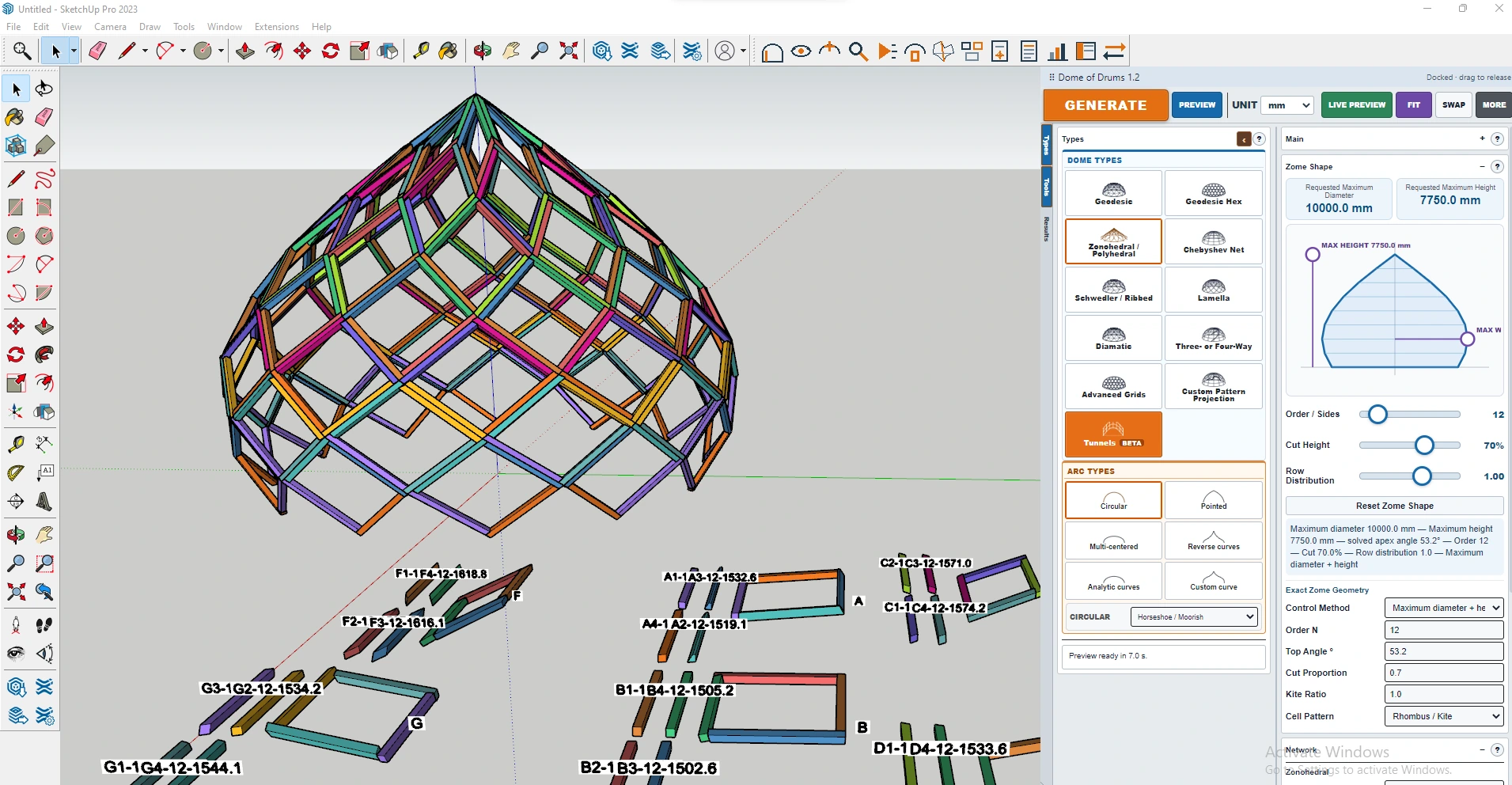
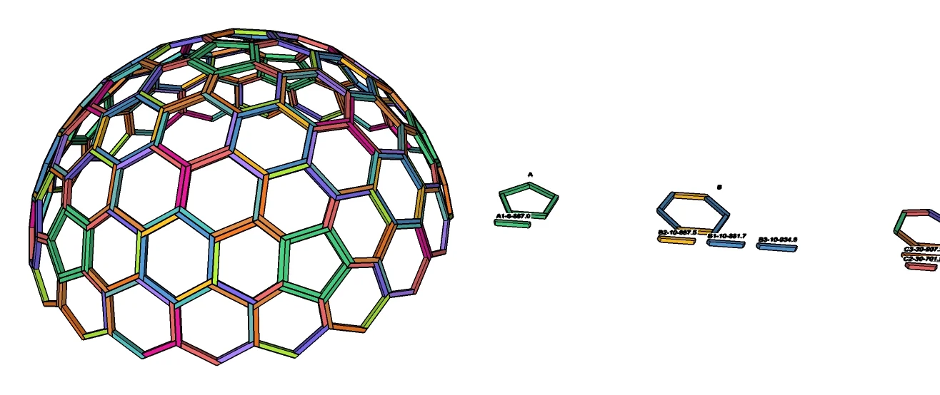
GeodesicGeodesic HexZonohedral / PolyhedralZome / Polar ZonohedralChebyshev NetSchwedler / RibbedLamellaDiamaticThree-Way GridFour-Way GridKagomeSpiral DiagridPhyllotaxisGreat-Circle NetworkPost-Formed Gridshell
ARCH & PROFILE LIBRARY

Choose the section before you build the shell.

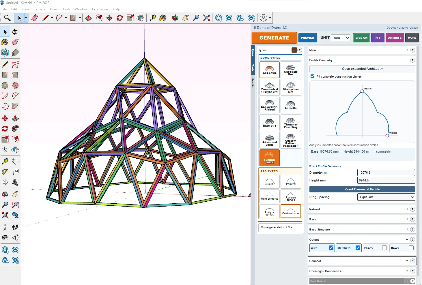
The profile system includes a broad architectural profile library.

CUSTOM GEOMETRY

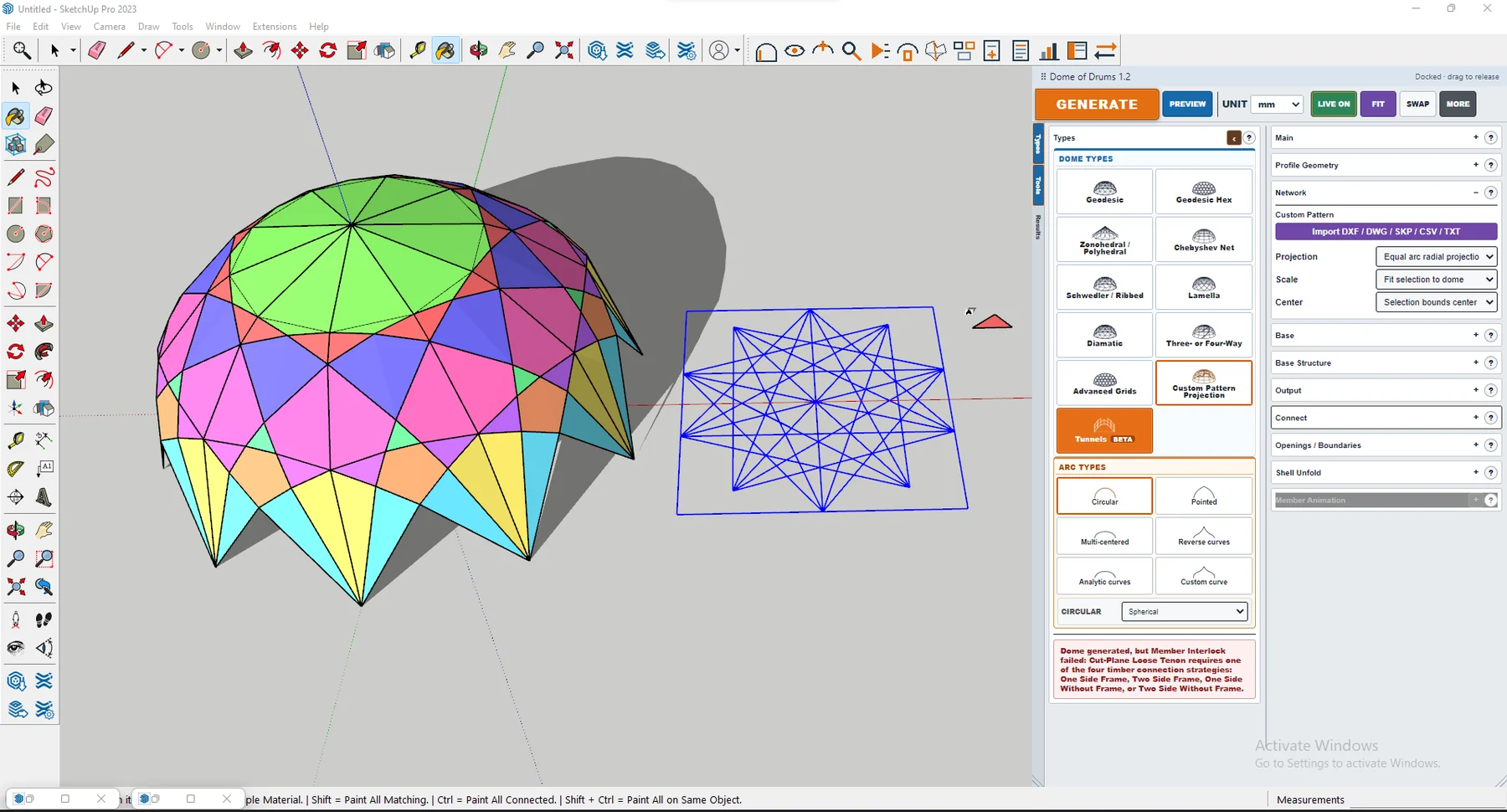
Project your own network

Import or select a 2D line pattern and project it onto the selected shell.

BUILD

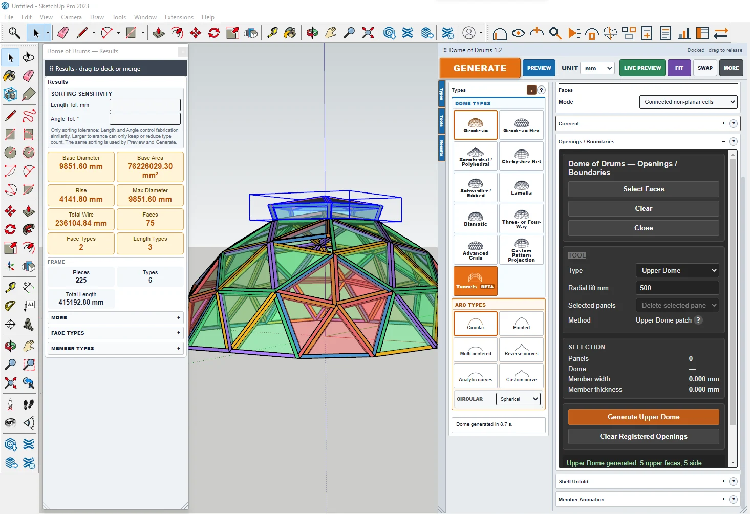
Physical members, connections and openings

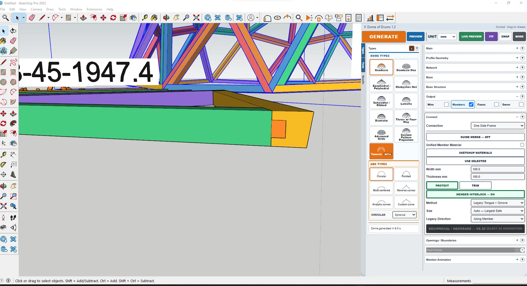
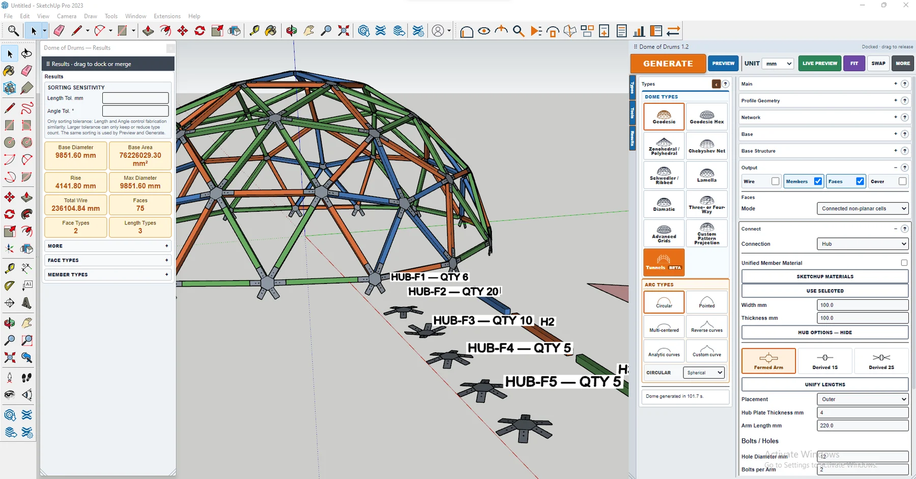
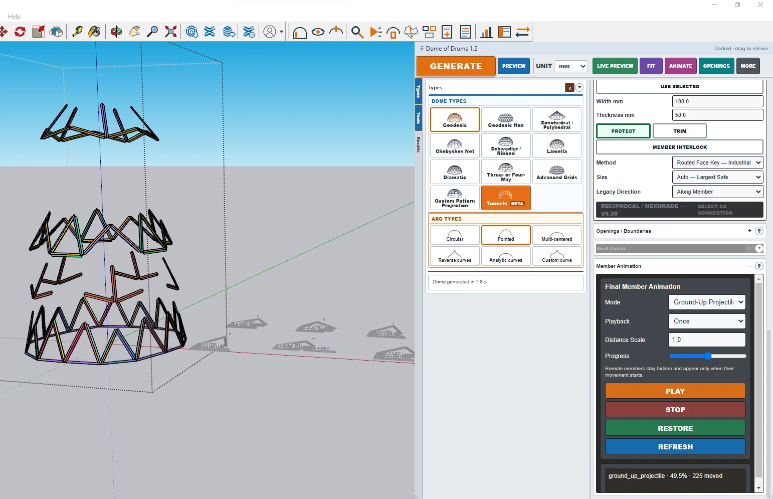
Structural members are physical objects, not abstract lines.

FABRICATION CHECK

The model should reveal problems, not hide them.

Physical member geometry helps reveal fabrication problems before material is cut.

FABRICATE

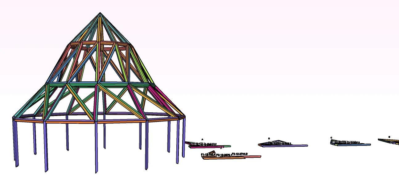
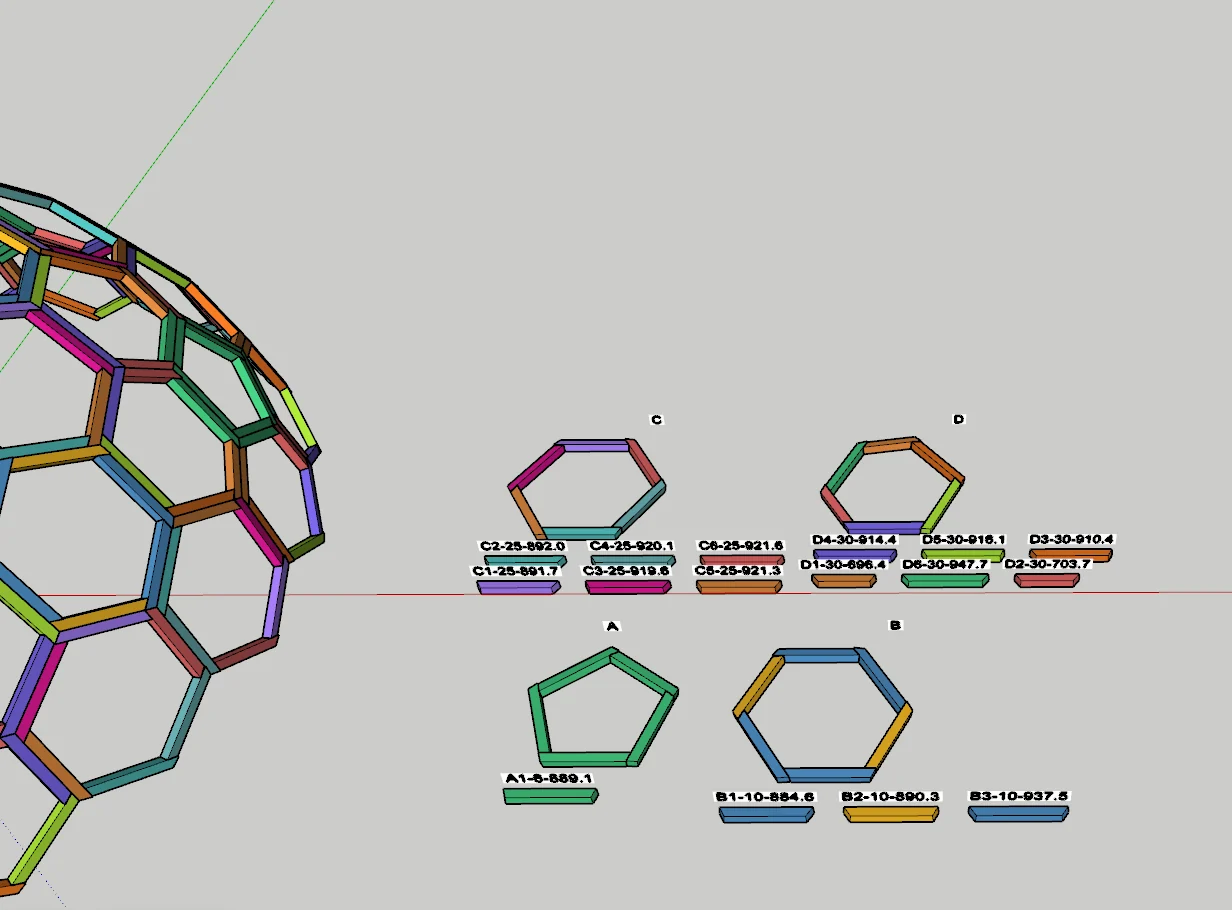
Classification, covers, molds and reports

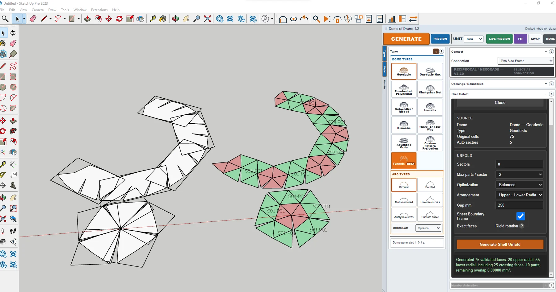
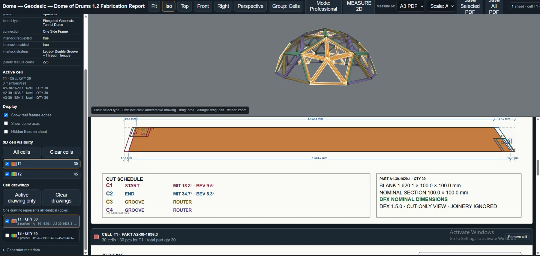
Translate the structure into workshop output.

ADDITIONAL WORKSHOP CAPABILITIES

From uneven ground to CAD-ready production files.

01 · SITE FIT

Ground Leveling & Base Alignment

Adjust and level the remaining base nodes, align the structure to the ground plane, and complete base-ring gaps where required. These tools help reconcile the geometric shell with its practical ground-contact conditions.

BASE NODES · LEVELING · GROUND ALIGNMENT

02 · DIGITAL FABRICATION

CAD & 3D Printing Export

Prepare individual design parts for downstream fabrication workflows, including AutoCAD-compatible DXF geometry and STL files for parts intended for 3D printing, such as hubs, connection components and suitable custom pieces.

DXF / AUTOCAD · STL / 3D PRINTING · PART-BASED EXPORT